
Pitch discipline
Joint layout becomes a program choice
The 650 A is programmed for two fixed pitch joints—25 mm and 50 mm—so the operator selects within a known production framework instead of creating a new arbitrary pitch.
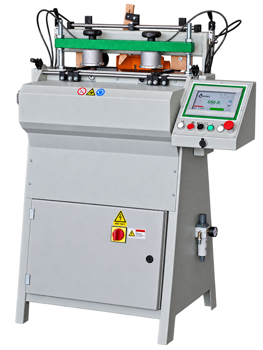
A two-axis OMEC milling machine for producing fixed-pitch dovetail and parallel joints in drawer and furniture components. The 650 A combines a single 16,500-rpm spindle, CNC-guided setup, pneumatic workpiece clamping and a 40-drawer-per-hour machine reference in a compact platform built around two fixed joint pitches: 25 mm and 50 mm.
Move fixed-pitch dovetail and parallel joint production away from repeated manual joint layout while keeping drawer dimensions and male/female part combinations inside a defined machine envelope.
The two-axis machine uses numerical control, one milling spindle and software-guided adjustments to run the 25 mm or 50 mm fixed-pitch joint program.
Single male, single female or male/female workpieces can be machined in the same platform, with manual pneumatic clamp/release control and a 40-drawer-per-hour machine reference.
Start with the manufacturing problem
The 650 A is built around a specific production problem: repeatable dovetail and parallel joint machining for drawer and furniture components where 25 mm or 50 mm pitch covers the product range and the workpieces fit the machine’s dimensional envelope.
The 650 A is programmed for two fixed pitch joints—25 mm and 50 mm—so the operator selects within a known production framework instead of creating a new arbitrary pitch.
The machine can cut single male parts, single female parts or male/female workpieces simultaneously.
Drawer length, width, front thickness, side thickness and joint height must all fall inside the specified workpiece limits.
The machine reference is 40 drawers/hour. Actual plant output still depends on workpiece handling, material, tooling, part mix and downstream assembly.
Application fit
The 650 A makes sense when the product family fits 25 mm or 50 mm center-to-center joint spacing and the required workpieces remain inside its dimensional range. Shops requiring freely variable pitch or broader CNC joint programming should qualify another OMEC route rather than forcing this model beyond its intended scope.
A direct fit for manufacturers producing drawer fronts, sides and related components with dovetail or parallel joints.
OMEC also positions the machine for various furniture elements where the same joint logic and dimensional range apply.
Useful when production requires single male, single female or simultaneous male/female workpiece machining.
If the product needs freely variable joint pitch, the 650 A’s two fixed pitch programs are a non-fit cue; qualify a more flexible OMEC numerical-control model.
Curved drawer fronts require application review before this model is specified for the job.
The machining system is automatic, while workpiece clamping and release are manually actuated through pneumatic valves.
Select the process from the part backwards
The right 650 A application is defined by joint type, pitch and workpiece envelope before horsepower or machine footprint enter the decision.
Confirm dovetail or parallel joint and whether the job uses single male, single female or simultaneous male/female machining.
The 650 A program is built around those two fixed center-to-center values.
Validate length, width, joint height, front thickness and side thickness against the exact OMEC limits.
Match the cutter profile and material to the joint and finished product using the available integral-HM/Widia and optional diamond cutter routes.
Check operator handling, compressed air, dust collection and the downstream gluing/assembly step before setting the line-output expectation.
Machine architecture / work cycle
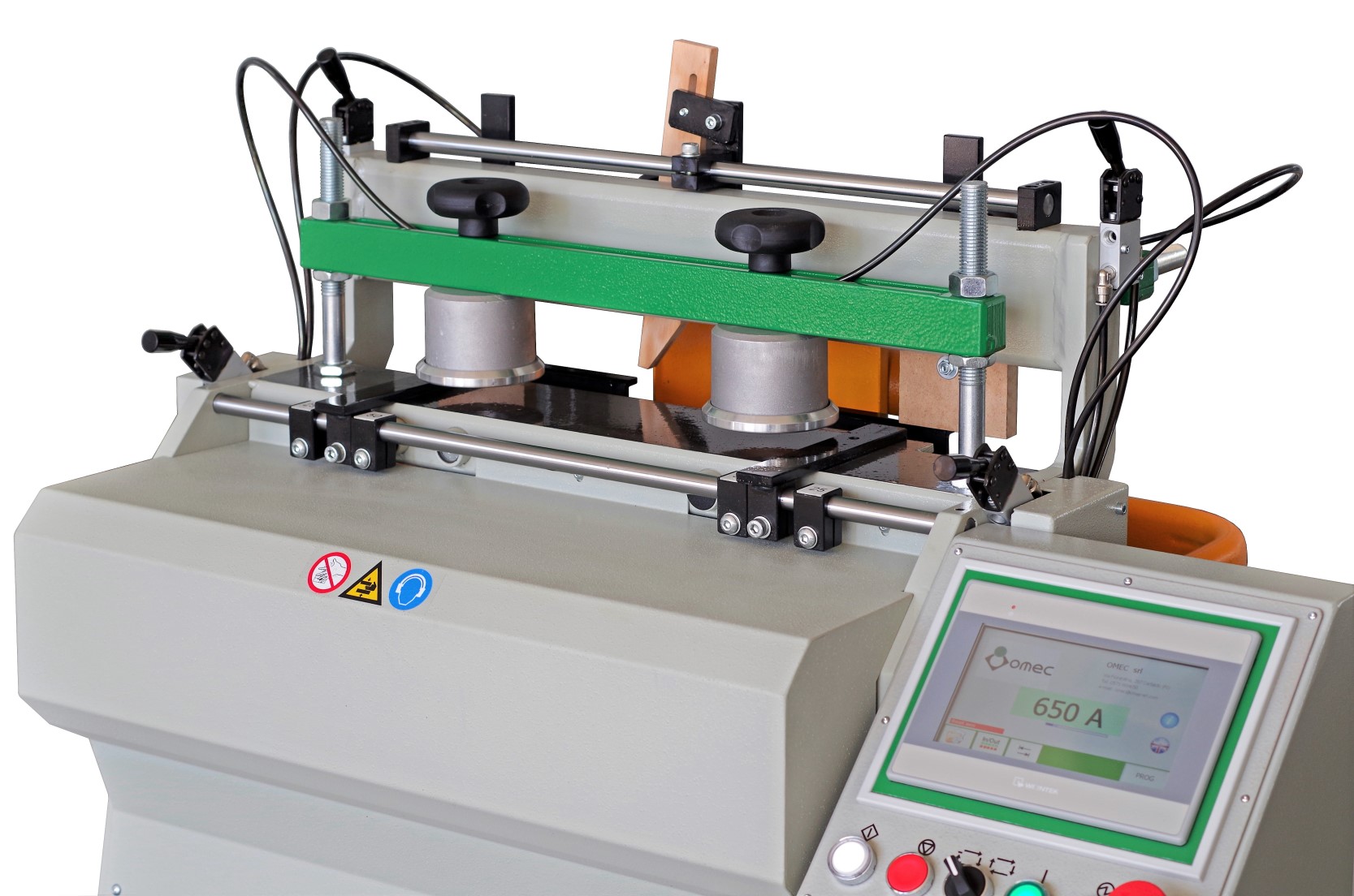
The 650 A is an automatic two-axis milling machine with numerical control. It uses one spindle and cutter, while workpieces are clamped and released manually through pneumatic valves.
The 650 A’s automatic milling architecture is built around two axes under numerical control.
The machine uses one spindle operating at 16,500 rpm.
Clamping and release are manual actions carried out with pneumatic valves.
The control displays machine software instructions on the monitor to guide the operator through available setup adjustments.
Joint capability
The 650 A machines dovetail and parallel joints. Male and female workpieces can be processed individually or together, while the control is programmed around two fixed pitch choices.
Joint examples
The 650 A supports multiple joint forms using original OMEC integral-HM tooling. The standard machine includes an integral-HM/Widia cutter installed, with optional HM and diamond cutter variants available for specific joint and finish requirements.
Technical framework
Core 650 A technical values are shown below. Metric values remain primary, with useful North American conversions shown in brackets.
| Field | Machine value | North American reference |
|---|---|---|
| Machine type | Two-axis automatic milling machine with numerical control / CNC system | Fixed-pitch dovetail / parallel-joint machine |
| Installed power | 2.5 kW | ~3.35 hp |
| Working pressure | 0.7 MPa | ~101.5 psi |
| Spindle | 1 | Single-spindle architecture |
| Spindle speed | 16,500 rpm | 16,500 rpm |
| Joint pitch / center-to-center | 25 or 50 mm fixed pitch | ~0.984 or 1.969 in |
| Drawer production | 40 n/h | 40 drawers/hour machine reference |
| Machine weight | 171 kg | ~377 lb |
| Packed machine weight | 221 kg | ~487 lb |
| Overall dimensions L × W × H | 97 × 76 × 137 cm | ~38.2 × 29.9 × 53.9 in |
| Packing dimensions | 122 × 87 × 153 cm | ~48.0 × 34.3 × 60.2 in |
Final voltage, phase and frequency are defined in the proposal for the supplied installation.
Dimensional range / workpiece envelope
Minimum and maximum workpiece dimensions are defined for length, width, joint height, front thickness and side thickness. Those limits are central to application qualification.
Use the dimensional limits below to qualify the actual drawer components before final machine selection.
Controls / automation / operator workflow
The 650 A performs automatic two-axis milling under numerical control, while clamp and release are manually actuated with pneumatic valves.
Commands are issued through a push-button/control-panel system with numerical control.
The CNC system is programmed for two fixed-pitch joint types: 25 mm and 50 mm.
Adjustments can be carried out following machine-software instructions displayed on the monitor.
The machine uses pneumatic valves for the operator-actuated workpiece clamping and release step.
Tooling architecture
The 650 A uses original OMEC cutters in integral HM, with a Widia/integral-HM cutter included as standard machine equipment. Optional 14 mm HM and diamond cutter variants are available for specific joint and finish requirements.
The standard configuration includes an integral-HM/Widia cutter mounted on the machine.
Optional Ø14 integral-HM cutters are available, including a version with a deburring tool.
A Ø14 cylindrical integral-HM cutter is available as an optional tool.
A Ø14 diamond milling cutter is available as an option.
A Ø14 diamond cutter with deburring tool is available as an option.
Option A05 is available for machining small pieces. Its exact supported workpiece range is confirmed during application review.
Pneumatics / extraction / utilities
The machine working pressure and installed power are defined below. Final dust-extraction airflow and electrical voltage, phase and frequency are confirmed for the supplied installation.
Working pressure is 0.7 MPa—approximately 101.5 psi.
OMEC labels this as on-board machine installed power. It is not rewritten as spindle-motor power.
Voltage, phase, frequency and branch protection are completed for the selected installation.
Machining requires a dust/chip strategy. Final extraction connection, airflow requirement and system interface are completed in the proposal.
Plan clearance for loading, unloading, control-panel access and service without using the compact footprint to block the machine’s working zone.
Final utility checks, machine setup, guarding and operator training belong to the qualified installation/commissioning scope.
Production-rate framework
The machine reference is 40 drawers per hour. Sustained plant throughput still depends on the actual drawer, operator handling, cutter, material and downstream assembly.
Machine reference: 40 drawers per hour. Actual sustained output depends on the drawer mix, handling, setup and surrounding process.
Changing drawer sizes, front/side combinations and batch sequence can affect handling around the machining cycle.
Cutter choice and actual material influence the process window and finished joint requirement.
A dovetail machine cannot raise finished-drawer output above a downstream gluing or pressing bottleneck without the rest of the line being balanced.
Ownership / service / changeover
The 650 A’s fixed-pitch scope simplifies what the machine is being asked to do, but consistent production still depends on cutter condition, workpiece preparation, pneumatic supply, dust/chip control and disciplined setup.
The 650 A is a two-pitch machine. Keep 25 mm and 50 mm joint programs tied to the intended drawer construction.
Treat cutter condition and correct OMEC tooling as part of joint quality and production planning.
Stable pneumatic supply and correct workpiece presentation support repeatable clamping before each machining cycle.
Preserve access to the cutting area, control panel and machine cabinet for qualified maintenance and inspection.
Production-line integration
A useful 650 A project maps the machine between prepared drawer components upstream and gluing/assembly downstream, then checks whether the surrounding process can support the intended drawer rate.
Bring front, side and mating components to the required dimensions and material condition.
Use the 650 A for the selected dovetail or parallel joint program and matching male/female workpiece arrangement.
Move machined components into the qualified adhesive process where the drawer construction requires gluing.
Press or clamp the drawer with a process sized for the product geometry and target output.
Compare the 650 A’s 40-drawer-per-hour machine reference with actual upstream preparation and downstream assembly capacity.
Valid configurations / options
Standard equipment and optional equipment are separated so tooling and special workpiece equipment can be specified correctly.
Standard equipment includes an integral-HM/Widia cutter installed, adjustment/maintenance tool kit and user/instruction manual.
Option for machining small pieces. The supported workpiece range is confirmed at quotation.
A24, A25 and A27/04 cover listed Ø14 integral-HM cutter variations.
A47 and A48 are Ø14 diamond cutter options, with A48 adding a deburring tool.
Final voltage, phase and frequency are tied to the machine supplied for the installation.
Extraction connection and system requirements are completed against the final machine installation.
Business-case framework
Use the business case to compare joint layout and machining effort, drawer mix, operator handling, cutter/tooling cost, downstream assembly and required output.
Measure current setup, machining and handling time for the exact drawer family.
Separate high-run fixed-pitch drawers from products that require a different joint pitch or special geometry.
Compare joint machining against gluing, pressing and final drawer assembly capacity.
Include cutter strategy, compressed-air service, extraction, installation and operator training in the real project scope.
Application data package
The fastest way to qualify a 650 A is to compare the finished joint and every critical workpiece dimension directly against the OMEC envelope.
Length, width, front thickness, side thickness, joint height and mating-part arrangement.
Dovetail or parallel joint, 25 mm or 50 mm pitch, male and/or female arrangement and required finished appearance.
Current drawer output, target output, batch sizes, product mix and current bottleneck.
Electrical service, compressed-air supply, dust collection, available floor space and upstream/downstream equipment.
Complete at quotation
Your complete OMEC 650 A proposal defines the exact machine configuration, 25 mm or 50 mm joint program, workpiece dimensions, male/female machining arrangement, cutter package, standard and optional tooling, electrical configuration, 0.7 MPa compressed-air interface, dust-extraction connection, machine/packing dimensions, weight, guarding, commissioning and expected role in the drawer-production process.
The proposal also confirms whether the part family is best served by the 650 A’s fixed-pitch architecture or requires a more flexible numerical-control approach.
650 A FAQ
The exact workpiece envelope and two pitch programs are the core qualification gates.
The 650 A machines dovetail and parallel joints for drawers and furniture components.
The 650 A uses two fixed center-to-center pitches: 25 mm and 50 mm.
Yes. The machine can process single male parts, single female parts or male/female workpieces simultaneously.
Workpiece length is 200–1500 mm, width 60–400 mm, joint height 8.5–16 mm, front thickness 8–60 mm and side thickness 7–25 mm.
The machine reference is 40 drawers per hour. Complete-line output still depends on the drawer mix, handling, setup and surrounding process.
The machine uses one spindle at 16,500 rpm.
Working pressure is 0.7 MPa, approximately 101.5 psi.
Standard equipment includes an integral-HM/Widia cutter installed, a tool kit for adjustment/maintenance and the instruction/user manual.
Yes. Ø14 diamond cutter options are available, including a version with a deburring tool.
The final supplied voltage, phase and frequency are defined in the quotation and installation documentation.
OMEC 650 A application review
Titan can qualify the 650 A against the actual workpiece envelope, 25 or 50 mm pitch requirement, male and/or female arrangement, target drawer output, tooling, utilities and the upstream and downstream process.
Useful inputs: drawer length and width, front thickness, side thickness, joint height, dovetail or parallel joint, 25 or 50 mm pitch, current output, target output, material, electrical service, compressed air, dust collection and downstream gluing/pressing method.